 Remove the Hydraulic Cylinder Pivot Pins
Once you finally win the battle against the Sikaflex and remove the covers on both sides (yes… all six covers), you can move to the next step.
Tools used:
 one BIG hammer one solid pin drift
Since we were clearly missing a team of heavily tattooed shipyard professionals, we did what any determined Ovni owner would do:
we built our own crane.


Well done on documenting this!!
Mike H
Pelerin
#104
hi ! please could you send me this complete file regarding removing the central board of my boat: my boat is OVNI435 number 2 built in year 2001. I am indicating the dedicated mail address regarding my boat only.
This address ist: xxxxxxx
Could you provide me with the translation in French language ?
I would be grateful to you if you could do this for me,
with my very best regards.
Cette histoire en français:
Comment démonter et réinstaller la dérive de l’Ovni 435 (Guide DIY)
Travailler sur la dérive d’un voilier aluminium à quille relevable fait partie de ces opérations qui semblent absolument terrifiantes… jusqu’à ce que l’on respire un grand coup, qu’on prépare un café, et qu’on découpe le travail étape par étape.
Du moins, ça a été mon expérience.
Sur SV Tatooine (Alubat Ovni 435), nous avons dû déposer la dérive (version légère — sans ballast) pour inspection, nettoyage et remise en état. Et comme la documentation correcte est… disons… mystérieusement rare, j’ai décidé de partager exactement comment nous avons procédé.
Bonne nouvelle : ce travail est tout à fait réalisable — même sans une équipe de super-héros musclés de chantier naval.
Nous, en tout cas, on ne l’avait pas.
⚠️ Cette procédure concerne la dérive légère (non ballastée) de l’Ovni.
Mettre la dérive en position haute et la sécuriser
Commencez par remonter complètement la dérive en position haute.
Depuis l’extérieur du bateau, bloquez-la mécaniquement pour qu’elle ne puisse pas redescendre.
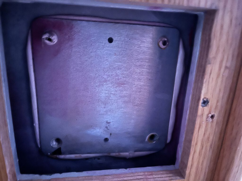
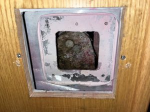
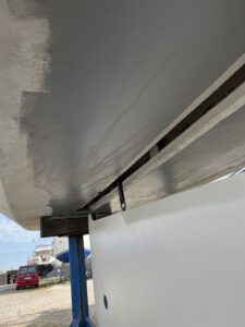
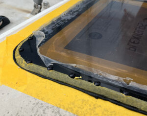
Dépose des plaques latérales (alias l’enfer du Sikaflex)
Étape suivante : retirer les vis qui maintiennent les trappes d’accès.
Ça paraît simple.
Ça ne l’était pas.
Alubat — dans son grand enthousiasme pour que les choses restent définitivement en place — avait appliqué ce qu’on peut seulement décrire comme des quantités industrielles de Sikaflex.
Résultat : un vrai cauchemar.
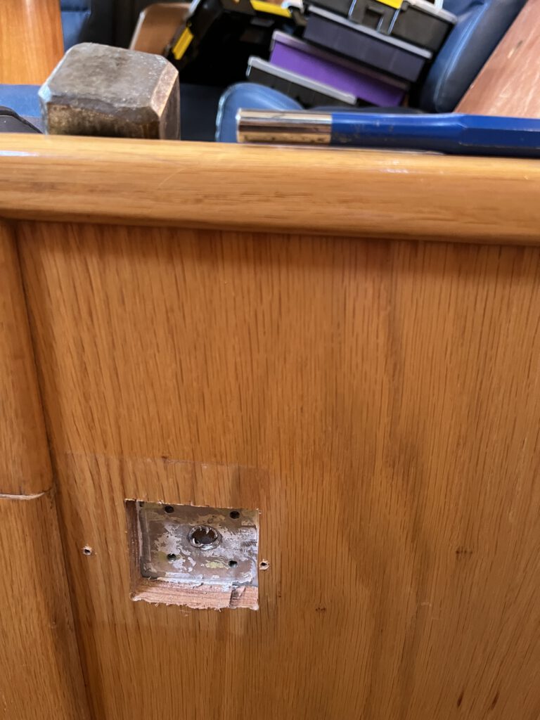
En théorie, les trous filetés centraux servent à visser des vis pour extraire la plaque.
Bonne idée. Le problème sur notre bateau était simple :
la plaque est trop fine
l’adhérence du Sikaflex est extrêmement forte
et les filetages… ont abandonné avant la colle
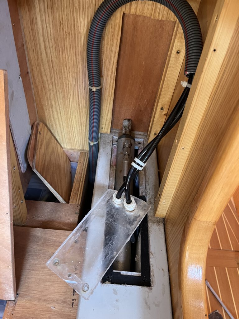
Retrait des axes du vérin hydraulique
Une fois la bataille contre le Sikaflex gagnée et les trappes retirées des deux côtés (oui… les six trappes), vous pouvez passer à l’étape suivante.
Outils utilisés :
un GROS marteau
un chasse-goupille solide
Sortie du vérin hydraulique
Une fois les axes retirés :
Pompez le vérin vers le haut avec le système hydraulique pour gagner du jeu.
Le vérin devrait alors pouvoir sortir.
Avant d’aller plus loin, les flexibles hydrauliques doivent être déconnectés.
Et c’est le moment où ça peut devenir… éclaboussant.
Je recommande fortement (retour d’expérience) :
prévoir un bidon vide
garder des chiffons à portée de main
Nous avons également :
percé un trou en haut de la dérive
installé un anneau de levage robuste
utilisé cet anneau comme point de support externe
Cela permet de maintenir la dérive suspendue en sécurité pendant la suite des opérations.
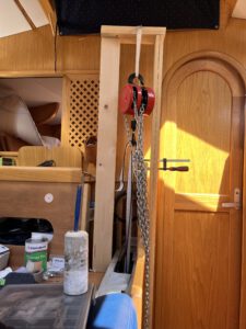
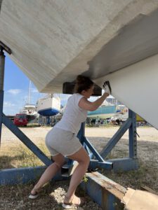
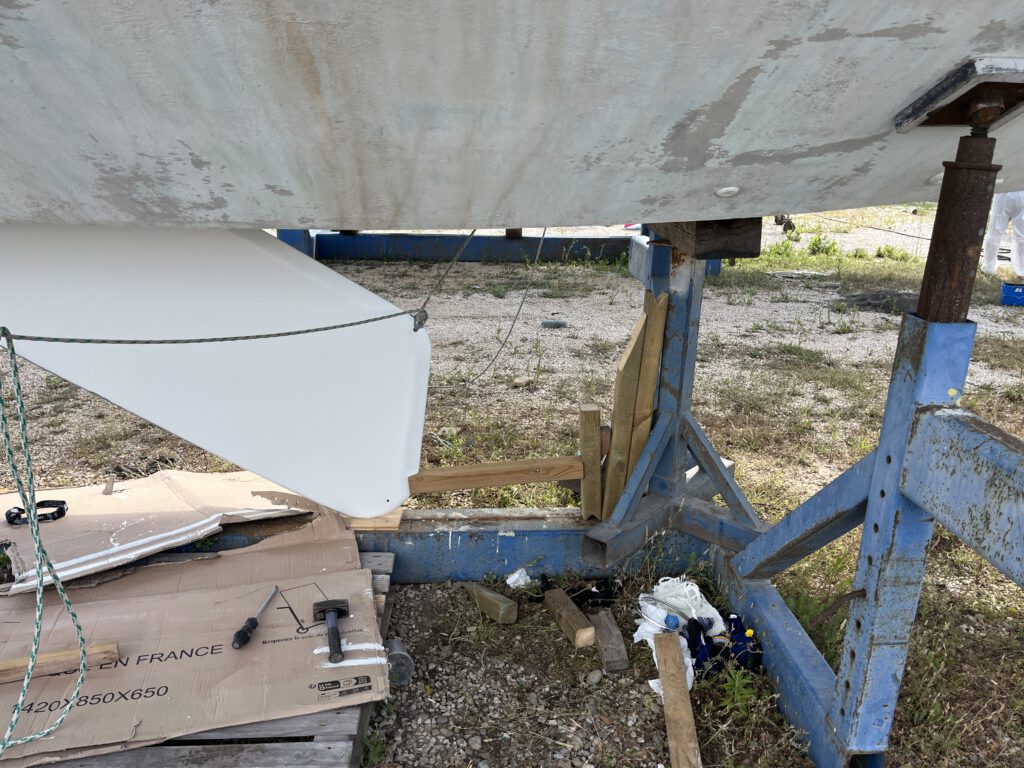
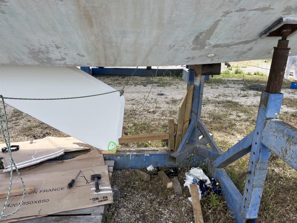
Fabriquer une « grue de chantier low-cost »
Comme nous manquions clairement d’une équipe de professionnels tatoués de chantier naval, nous avons fait ce que tout propriétaire d’Ovni déterminé ferait :
👉 nous avons construit notre propre grue.
Une fois la grue en bois en place, l’étape suivante consiste à fixer le palan à chaîne sur l’anneau de dérive.
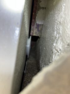
Chasser l’axe principal de dérive
Avec le vérin retiré, la dernière chose qui maintient la dérive est l’axe principal.
En théorie, on pourrait s’attendre à un système de verrouillage sophistiqué.
Il n’y en a pas.
C’est juste… serré.
Sur SV Tatooine, la procédure était magnifiquement simple et légèrement sportive :
👉 chasse-goupille solide + ÉNORME marteau + compréhension de l’inertie de masse.
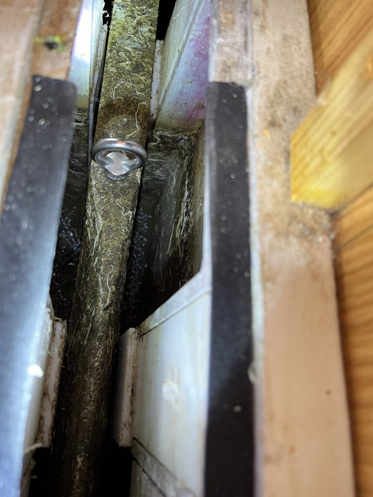
Descente de la dérive
Une fois l’axe principal retiré, la dérive est libre.
Enfin… presque.
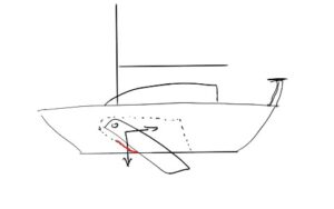
À ce stade, vous pouvez commencer à descendre la dérive, mais — et c’est important — elle ne descend pas verticalement.
Sur l’Ovni 435, le mouvement correct est :
vers le bas
et légèrement vers l’arrière du bateau
Pour libérer proprement la dérive, il faut guider soigneusement les bagues afin qu’elles passent le long des glissières longitudinales dans le puits de dérive.
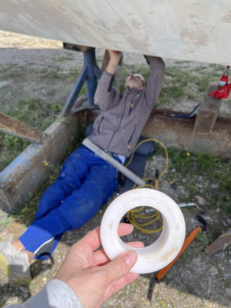
Vérifier la garde au sol
Voici quelque chose qu’on sous-estime très facilement… jusqu’à ce qu’on soit allongé sous le bateau avec une dérive qui refuse de sortir.
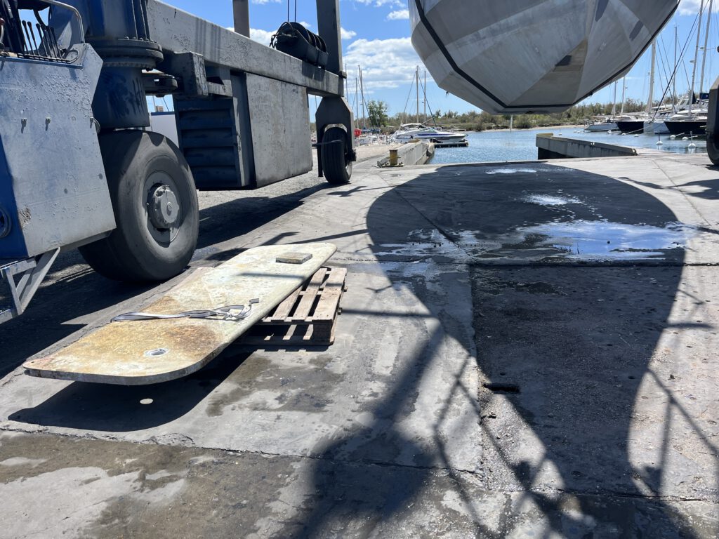
Sur SV Tatooine, le bateau était initialement trop bas sur ses bers.
Pour terminer correctement, nous avons dû demander au chantier de lever le bateau avec le travel lift.
Lors de la remise sur bers, nous avons demandé explicitement une position plus haute.
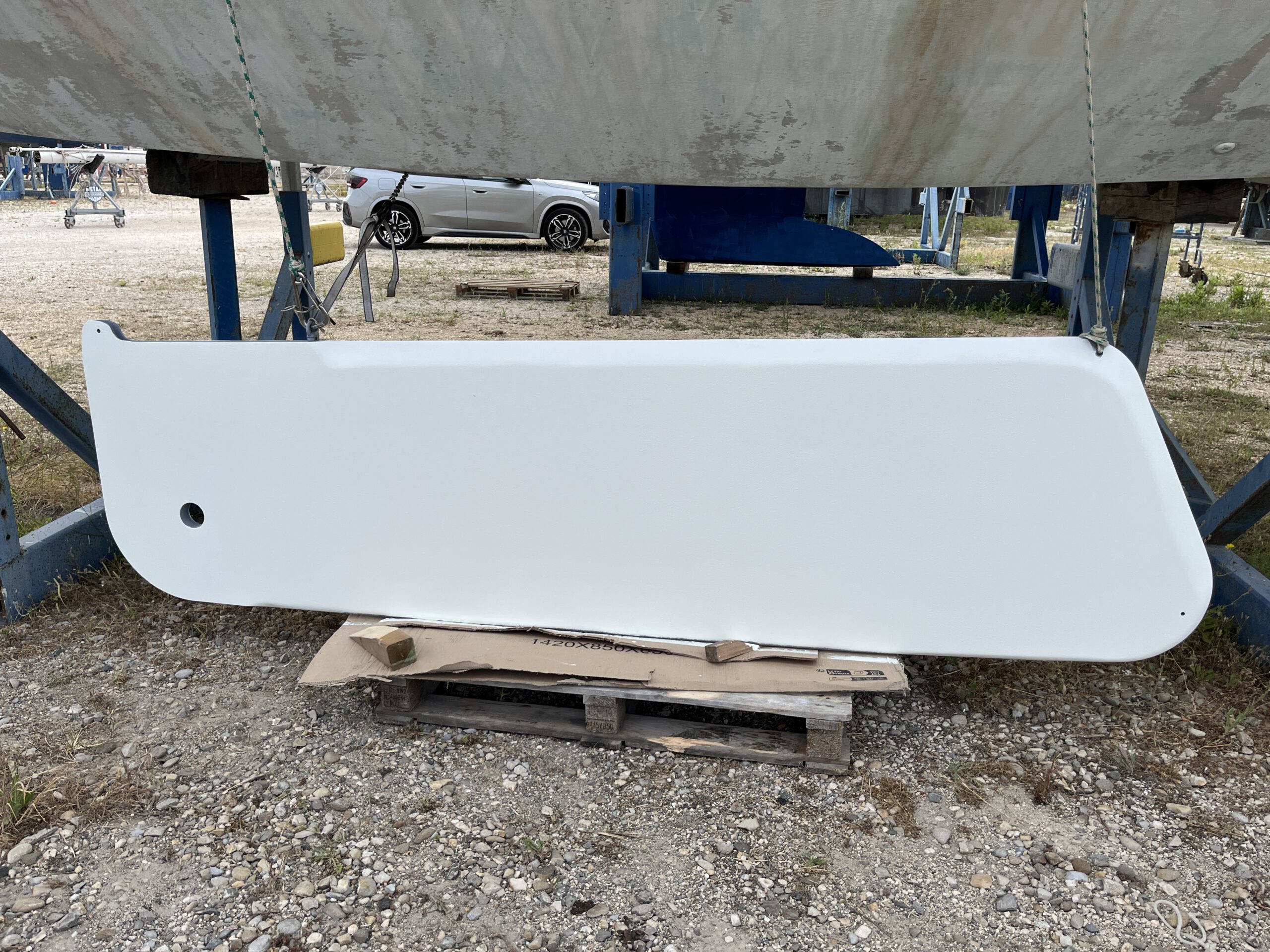
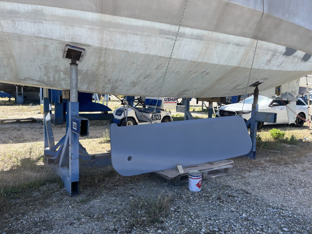
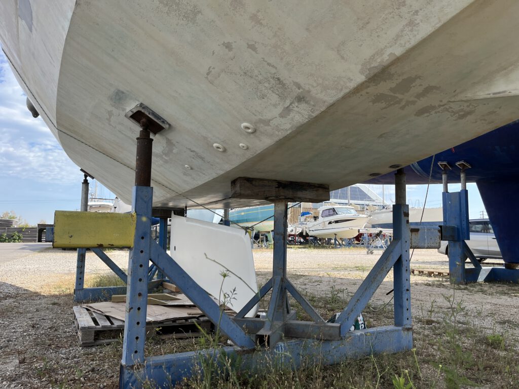
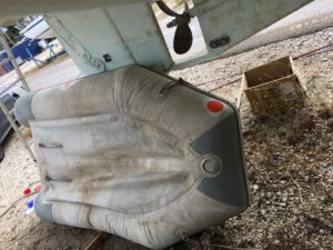
Résultat après remise en état
Une fois la dérive sortie, nous avons pu inspecter correctement la surface.
La dérive a été :
sablée par un professionnel
les défauts comblés à l’époxy
surface dressée
primaire de protection appliqué
Lorsque la dérive est revenue au bateau, comme neuve, nous l’avons sécurisée avec des aussières depuis le pont des deux côtés.
Cela nous a permis :
de la suspendre en sécurité
d’appliquer l’antifouling confortablement
Ensuite, ces mêmes aussières — renvoyées aux winchs — ont été extrêmement utiles pour guider précisément la dérive sous le bateau lors de la repose.
Réinstallation (partie délicate)
Comme nous ne pouvions pas retirer les glissières longitudinales, la repose a demandé un peu de gymnastique créative.
Lors de la remise en place :
Lever soigneusement la dérive
La guider au-delà des glissières
Installer les nouvelles bagues d’axe
Disons simplement…
👉 les petites mains deviennent un avantage stratégique.
C’est minutieux et légèrement acrobatique.
Remettre l’axe de dérive et s’occuper du vérin
Reconnexion et purge du vérin hydraulique
Avant de remettre le piston en place, nous avons d’abord reconnecté et rempli le circuit hydraulique.
Procédure :
Placer les deux flexibles dans un récipient rempli d’eau glycolée
Pomper poignée en position bas puis haut
Garder les flexibles immergés
Continuer jusqu’à disparition des bulles en position neutre
Serrer le raccord supérieur
Mettre poignée en position haute
Pomper jusqu’en butée
Passer en position basse et pomper
Remettre en neutre
Serrer le raccord inférieur
Pomper jusqu’extension complète
Effectuer deux cycles complets
Remontage du vérin
La méthode la plus simple pour nous a été :
Positionner le vérin dans le puits
Fixer d’abord l’axe inférieur
Pomper légèrement pour aligner l’œil supérieur
Aligner soigneusement
Insérer l’axe supérieur
Test final
Une fois tout remonté :
👉 tester plusieurs cycles complets montée / descente.
Sur SV Tatooine, nous avons vérifié :
mouvement fluide
aucun bruit anormal
aucune fuite hydraulique
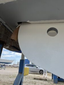
Ne pas oublier l’anode zinc
Dernière étape : installer une anode zinc à l’extrémité de la dérive pour prévenir la corrosion.
Petit détail, grande importance.
Correctement positionnée, l’anode n’empêche pas la remontée complète de la dérive tout en assurant une protection galvanique efficace.
Conclusion
Déposer et réinstaller la dérive de l’Ovni 435 (version non ballastée) est tout à fait faisable sans équipe de chantier naval complète.
Bon vent !
Maria — SV Tatooine